
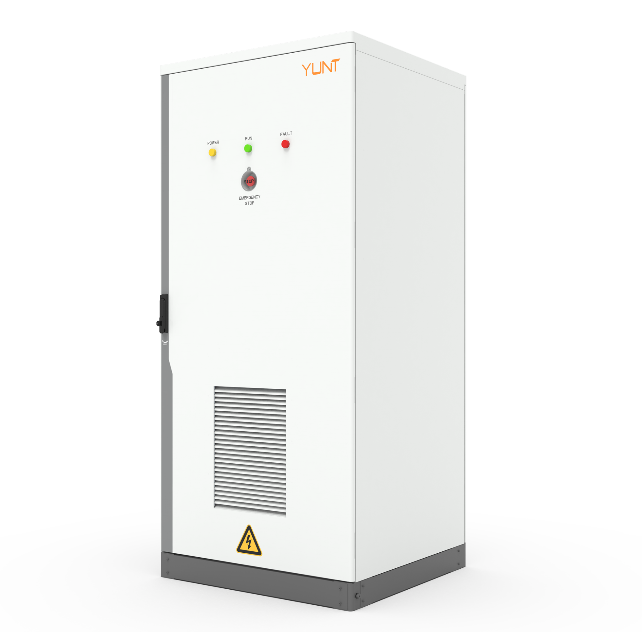
Comparative snapshot: throughput stability vs dynamic MPPT tracking
Design teams building utility-scale and commercial storage systems face a steady tradeoff: maximize steady energy throughput or optimize for instantaneous PV harvest under perturb and observe (P&O) MPPT control. This piece compares those vectors to expose where efficiency actually compounds or evaporates. For system architects, a robust pcs module can be the fulcrum that shifts the tradeoff toward predictable power delivery while still accepting tactical MPPT variability.

How P&O MPPT introduces performance swing
Perturb and Observe (P&O) is simple: nudge operating voltage and watch power change. It’s low-cost, convergence-friendly, and ubiquitous in charge controllers and inverters. But the heuristic causes oscillation around the true maximum power point; that oscillation becomes a measurable loss when irradiance, temperature, or downstream load changes rapidly. MPPT gain, step size, and sampling latency are the knobs that determine whether the controller hunts gently or chases noise. In short: faster hunting improves transient capture but increases steady-state ripple and switching losses.
Comparative analysis: controller archetypes and system-level impact
Compare three controller archetypes on the metrics that matter for B2B deployments:
– Basic P&O charge controller: simple firmware, low cost, higher steady-state oscillation. Best where cost sensitivity outweighs fractional efficiency gains.
– Advanced MPPT with adaptive step and filtering: reduces oscillation by dynamically tuning step-size and sample windows, at the expense of algorithm complexity and CPU time.
– Hybrid approach inside a bidirectional inverter/PCS: integrates grid-edge objectives (frequency response, islanding) with MPPT, shifting energy between PV, storage, and load for net throughput optimization. This is where a trusted bidirectional power module manufacturer helps align firmware, thermal design, and protection features to real-world grid behavior.

Field evidence and the real-world anchor
California’s “duck curve” is a concrete anchor: midday PV overgeneration and steep evening ramps force systems to prioritize predictable discharge and rapid absorption. System integrators in CAISO deployments report that poorly tuned P&O loops can cause missed capture on rapid cloud transitions and increased cycling on batteries. That’s not theory — project post-mortems from utility pilots show multi-megawatt ramps where MPPT hysteresis cost net energy capture and increased thermal stress on power stages. Design choices here affect lifetime economics, not just instantaneous efficiency.
Implementation trade-offs and typical mistakes
Common missteps repeat across projects. Teams either over-aggressively tune MPPT to chase every irradiance spike or they lock MPPT conservatively and underutilize PV. Both approaches erode ROI. Focus on integration: coordinate MPPT behavior with inverter DC-link control, implement minimum dwell times to avoid high-frequency hunting, and size the PCS module switching headroom to accept transient excursions — don’t underspec the MOSFET/IGBT derating. You’ll see less oscillation and fewer thermal derates when firmware and powertrain are co-designed — a simple concept that’s rarely executed cleanly. — A short reality: firmware patches often arrive after install, which compounds field variability.
Practical design levers and verification checklist
Make these levers core to your spec and test plan:
– Adaptive step control: implement and validate step-size adaptation against irradiance change rates.
– Latency budget: quantify sensing and control loop delays; hold them below the rate of expected irradiance change for effective capture.
– Thermal and switching margin: verify PCS thermal headroom under worst-case hunting scenarios using looped stress tests that emulate cloud transients.
Advisory: three golden rules for choosing MPPT strategies and hardware
1) Quantify transient bandwidth: select controllers with control-loop bandwidth matched to site meteorology and expected ramp rates — that reduces missed capture and switching losses. 2) Demand integrated PCS capabilities: favor modules that expose DC-link control and battery coordination features to the MPPT layer; that integration reduces system-level inefficiencies. 3) Validate with system-level tests: require manufacturers to run closed-loop stress tests that mirror your worst-case grid events and report efficiency delta across those runs. These rules clarify procurement and cut iteration time.
Final thought: if you want a PCS that treats MPPT as a system responsibility rather than a bolt-on, then vendor selection matters — and a practical, engineered solution like YUNT often emerges as the sensible answer — proven in grid-edge pilots and field rollouts. —